Table of Contents
1. APOLLO Optical Design
2. Solid Works Views of APOLLO
3. Side-Trim View
1. APOLLO Optical Design

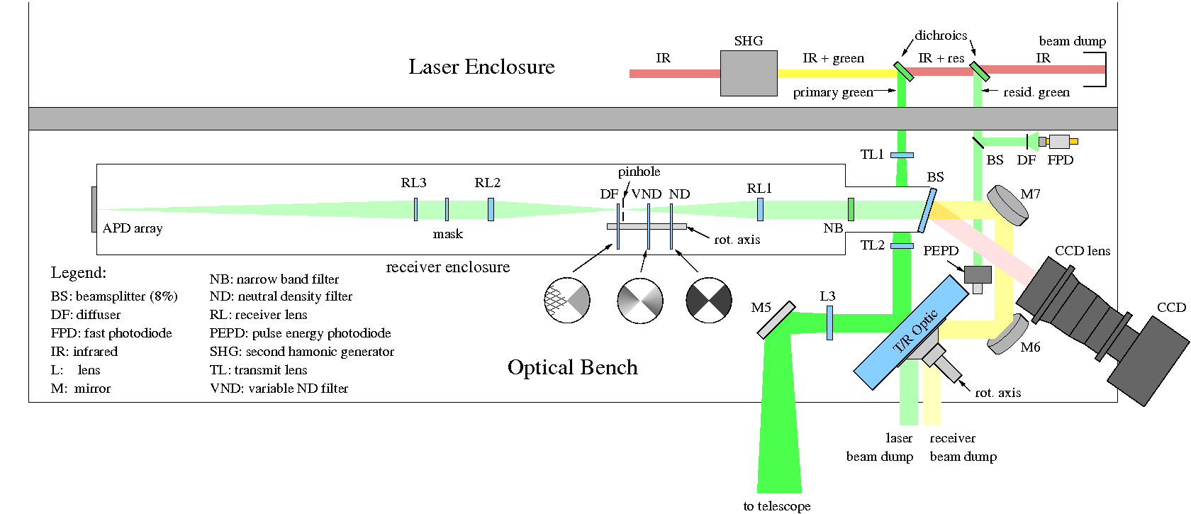
Transmit Path
Following the laser output, the 9 mm output beam is expanded to about 17 mm, relfected off the rotating mirror (transmit/receive switch, or T/R switch), expanded into an f/10 beam, and directed toward the telescope port.
Receive Path
Inbound light is collimated to 20 mm, passes through the T/R switch, and is folded up and into the receiver. At the receiver entrance is a beam splitter that sends 8% of the light to a CCD camera. Just beyond this is a norrow band filter permitting only green light into the rest of the receiver. Within the light-tight receiver enclosure is a 3-arcsecond spatial filter to further reduce background light, various baffles, and finally the APD. RL1 and RL2 are achromats, but optical performance is perfectly acceptable with all other lenses as singlets.
Variable Attenuation
A series of rotating disks on either side of the pinhole provide alternately clear and attenuated paths through the receiver. The disks are in the clear position at the time of lunar return, and with AR coatings are optically unobtrusive. For the fiducial return, these disks present a total of 4 orders of magnitude of attenuation. One of the disks has a variable attenuation, so that adjusting the phase of the disks relative to the T/R switch, it is possible to fine-tune the attenuation (across a factor of ten) to achieve the correct fiducial return rate of approximately one photon per pulse.Detector
The APD array itself has a lenslet array in front of it (at the focal plane), with 100 µm spacing and 0.5 mm focal length, forming a pupil image on each of the APD array elements.
Optics Actuation & CCD
Both the laser beam expander and the f/10 diverging/collimating lens utilize linear motion stages permitting adjustment of laser beam collimation and overall system focus. Additionally, one of the fold mirrors preceeding the receiver (M7) is tip-tilt adjustable allowing real-time co-alignment of the laser beam and the receiver. For satellite ranging, these need to be intentionally offset due to relativistic velocity aberration. For the moon, this is slightly less than one arcsecond, though worth controlling. Because the CCD and receiver are permanently aligned with respect to each other, a unique pixel on the CCD array can be associated with the center of the APD field, so that the CCD becomes a primary tool in target acquisition.
The T/R Switch & Calibration Attenuation
The T/R switch is a large, flat optic spinning at 20 Hz (1200 RPM). The rate can be adjusted slightly (and dynamically) to guarantee that lunar returns arrive 180° out-of-phase with the laser fire. The T/R switch is mostly clear, and anti-reflection coated, but has a small patch of high-reflectance multi-layer dielectric coating for reflecting the laser beam. This patch, in conjunction with a similar patch on the back side (the side away from the laser) provide 6 orders-of-magnitude of attenuation for the receiver, so that when the laser fires the receiver is shielded from backscatter along the optical train. This also—in conjunction with the spinning attenuators near the receiver pinhole— reduces the fiducial signal from the corner-cube prism within the telescope to the few-photon level at the APD array.
2. Solid Works Views of APOLLO

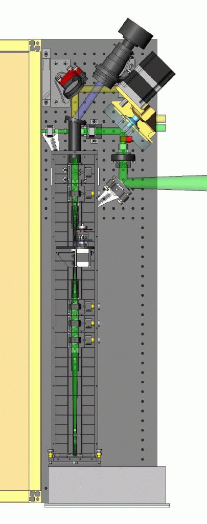
In the picture at top you can see most of the optical layout as well as both the outgoing and incoming light paths. Our Nd:YAG laser produces very short pulses (~95 ps FWHM) of green light (532 nm) at a repetition rate of 20 Hz. The paths of these pulses of laser light are represented as beams in our drawings.
The first two lenses that meet the outgoing laser light (green beam exiting box on left), expand the beam before it hits the reflective patch on our rotating optic. After reflection, the beam passes through a lens ("f/10 lens") which is positioned such that the outgoing beam is expanded to fill the primary mirror. The light exits the telescope as a collimated 3.5 m diameter laser pulse.
The light returning from the moon caught by the telescope is directed to our optical system, seen as incoming light from the right of the picture. It is collimated by our f/10 lens and passed through the rotating optic, which has by this time rotated the reflecting patch out of the way. In the picture the rotating optic's base is goldish in color. The motor is held above the optic and drives the optic via a pulley. This light that passes through this optic is represented as the yellow beam in the picture. It is steered toward the receiver unit (long rectangular box with slots) which will isolate the 532 nm laser light from the rest of the moonlight. The purpose of the receiver is to filter out our reflected laser signal (a few photons per pulse) from all the light from the moon, then focus that signal onto our APD detector array.
The angled snout at the front of the receiver box holds a narrow band filter which passes only green light and reflects all other wavelengths into our CCD camera. By imaging this reflected light we will be able to see where the receiver is looking on the moon's surface, although our actual ability to decipher what we are looking at is determined by the atmospheric seeing. It will be very important to keep stray light out of the receiver in practice, however in this drawing the top has been removed.
The optics in the receiver will be used to filter out the laser pulses returning from the retro-reflector arrays, from all the other light that has entered the telescope. The slots that run down the length of the box hold baffle plates which have been designed with apertures only slightly larger than that of the beam itself.
3. Side Trim View

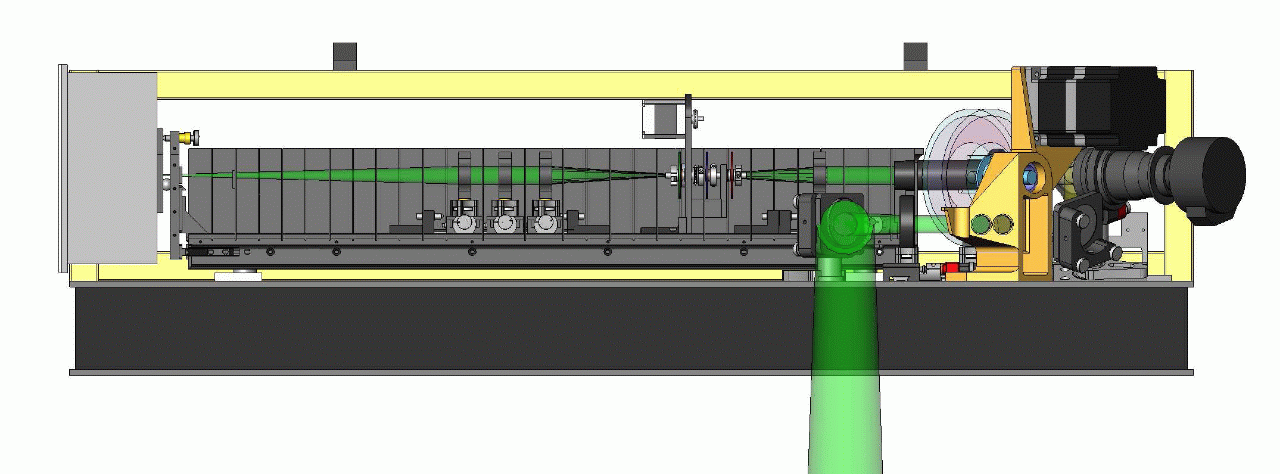
Here we see the inner workings of our receiver box. The collimated light entering the enclosure at the right has just passed through a narrow band filter positioned at the front of the receiver snout and consists only of 532 nm light.
From right to left, the first lens in the receiver box is the first component of our spatial filter. This lens focuses the beam into a point at the center of a 400 μm pinhole. The lens following the pinhole then re-collimates the beam. Just before the light reaches the pinhole, it passes through two rotating optics (red and blue disks in picture) which will be adjusted to control the desired attenuation of the beam. Just after the pinhole, the light will hit another rotating optic (green disk) that has a patch of frosted glass on it. This frosted glass will be used to diffuse the telescope's internal corner cube return but it will be rotated out of the way in time for the lunar returns.
The optical mount following the last spatial filter lens is used to hold a masking optic which defines the entrance pupil and central obscuration of our system. The final lens in the receiver focuses the signal down to a focus on our APD lenslet array which is held in our adjustable flexure-mounted APD box positioned at the end of the receiver. The lenslet array distributes the light evenly over our 16 element APD array (not seen in picture).


